What We Offer
- Solar Energy
- Wind Power Systems
- Gasifier Power Generation
- Power Factor Correction Systems
- UPS - Uninterrupted Power Supply Systems
- Hydro Power Systems

Power Factor
What is Power Factor?
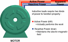
Special electrical requirement of inductive loads Most loads in modern electrical distribution systems are inductive. Examples include motors, transformers, gaseous tube lighting ballasts, and induction furnaces. Inductive loads need a magnetic field to operate. Inductive loads require two kinds of current: • Working power (kW) to perform the actual work of creating heat, light, motion, machine output, and so on. • Reactive power (kVAR) to sustain the magnetic field Working power consumes watts and can be read on a wattmeter. It is measured in kilowatts (kW). Reactive power doesn’t perform useful “work,” but circulates between the generator and the load. It places a heavier drain on the power source, as well as on the power source’s distribution system. Reactive power is measured in kilovolt-amperes-reactive (kVAR). Working power and reactive power together make up apparent power. Apparent power is measured in kilovolt-amperes (kVA).
Fundamentals of power factor
Power factor is the ratio of working power to apparent power.
It measures how effectively electrical power is being used. A high
power factor signals efficient utilization of electrical power, while
a low power factor indicates poor utilization of electrical power.
To determine power factor (PF), divide working power (kW) by
apparent power (kVA). In a linear or sinusoidal system, the result
is also referred to as the cosine θ.
.
For example, if you had a boring mill that was operating at 100 kW
and the apparent power consumed was 125 kVA, you would divide
100 by 125 and come up with a power factor of 0.80. Note: A right power triangle is often used to illustrate the relationship
between kW, kVAR, and kVA.
PF = = cosine θ kVA
kW
= (PF ) 0.80
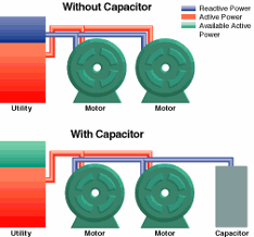
Where should I install Capacitors?
Where should I install capacitors in my plant distribution system? At the load Because capacitors act as kVAR generators, the most efficient place to install them is directly at the motor, where kVAR is consumed. Three options exist for installing capacitors at the motor.
Location A—motor side of overload relay
- New motor
installations in which overloads can be sized in accordance with reduced
current draw
- Existing motors when no overload change is required
Location B—line side of starter
- Existing motors when overload rating surpasses code
Location C—line side of starter
- Motors that are jogged, plugged, reversed
- Multi-speed motors
- Starters with open transition and starters that
disconnect/reconnect capacitor during cycle
- Motors that start frequently
- Motor loads with high inertia, where disconnecting the motor with the capacitor can turn the motor into a self-excited generator.
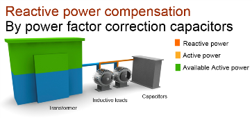
At the Service Feeder
When correcting entire plant loads, capacitor banks can be installed at the service entrance, if load conditions and transformer size permit. If the amount of correction is too large, some capacitors can be installed at individual motors or branch circuits. When capacitors are connected to the bus, feeder, motor control center, or switchboard, a disconnect and overcurrent protection must be provided.